EngineeringDiscuss a project
Power electronics · Resonant circuit · Control
Converter technology for industrial induction systems
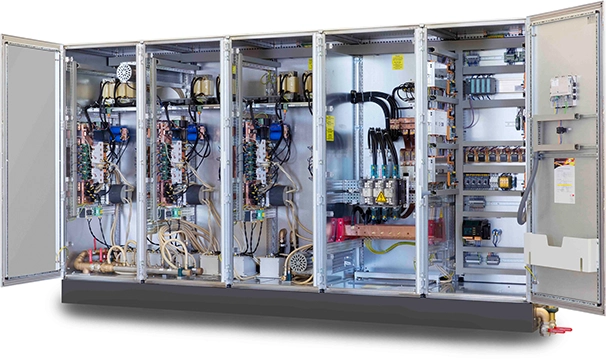
HBB Induction dimensions the power supply from the plant grid to the induction load, including transformer, rectifier, DC link, power stage, capacitor bank, cooling and control.
01
Topology matched to power and frequency
Large low-frequency melting systems have different requirements from medium- or high-frequency heating processes. Power, frequency range, load dynamics and grid structure determine the topology.
Solutions include IGBT/MOSFET bridges, thyristor converters, direct converters and multi-output concepts.
- 50 Hz to high frequency
- Series and parallel resonance
- Single and multiple outputs
02
Grid, rectifier and DC link
Transformer, phase shift, rectifier, reactor, capacitors and pre-charge are dimensioned for load steps and continuous duty.
Ripple and thermal loading define the DC-link components and protection.
- 6- and 12-pulse concepts
- DC-link capacitance and reactor
- Pre-charge and protection
03
Resonant circuit, cooling and control
Converter, matching transformer, capacitor bank, conductors and load form one electrical system. Resonance, phase angle, impedance and quality factor must remain within safe limits.
Digital control, PLC/HMI, Profinet, trends and event recording support transparent operation and diagnosis.
- Capacitor bank and matching
- Power/current/frequency control
- Diagnostics and protection
HBB Induction
Evaluate converter and load together
Provide grid voltage, power, output voltage, frequency range, load data and existing resonant-circuit components.
HBB Induction EngineeringContactinfo@hbb-induction.com